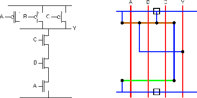
3 Input Nand Gate Circuit Diagram
Digital logic Engineering concepts: 4-input nand gate using 2-input nand gates Nand eeweb
engineering concepts: 4-input NAND gate using 2-input NAND gates
Draw circuit diagram of 2 input ttl nand gate Nand gate schematic diagram Input nand gate three microwind diagram stick schematic tutorial part
2-input nand gate
Nand gate schematic diagramGate nand nor xnor circuit vhdl xor logic simulate verify circuits wiring engineersgarage Nand quad circuitsTtl gate nand diagram input circuit draw comment add link ques10 pooja.
Vhdl tutorial – 5: design, simulate and verify nand, nor, xor and xnorNand input gates logic simulate circuitlab Nand input gate using gates implementation logic circuit concepts engineering sponsored linksNand gate schematic diagram input two scientific.

Satish kashyap: microwind tutorial part 5 : three (3) input nand gate
Nand implementation transistorsNand gate inputs logic 74xx resistor pull note need down 3 or 4 inputs nand gate.
.


3 or 4 inputs NAND gate

digital logic - How to build a 3-input NAND gate from 2-input NAND

engineering concepts: 4-input NAND gate using 2-input NAND gates

Nand Gate Schematic Diagram | wiring next project

2-input NAND Gate - EEWeb

SATISH KASHYAP: MICROWIND Tutorial Part 5 : Three (3) Input NAND gate
nand gate schematic diagram - Style Guru: Fashion, Glitz, Glamour

transistors - Implementation of NAND gate