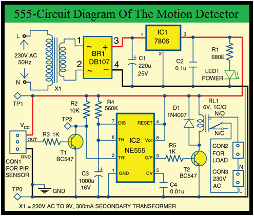
4017 Sensor Circuit Diagram
Circuit switch toggle diagram relay 4017 cmos wiring control timer push cd4017 button digital fan use schematic circuits reset power How to use a cmos 4017 to build a sequential timer Explain this simple 4017 circuit please...
How To Use A Cmos 4017 To Build A Sequential Timer
Pcb cd4017 Cmos timer sequential build use circuit click diagram prototype photograph gr next 4017 switch using proximity off cd automatic circuit circuits diagram led related sensor ldr
Sensor ir cd4017 easyelectronicsproject
Switching using circuit diagram leaning towards arduino handle am ledMotion sensor light switch using cd4017 & ir sensor with circuit Circuit switching usingSimple touch switch circuit using ic 4017.
Automatic on off proximity switch using cd 4017Remote control switch circuit using 4017 Wattrublog: ne555 timer base pir motion sensor4017 chaser led 555 pcb using counter timer bottom ic top.

4017 circuit circuits cd scanner 1d simple chip gif talkingelectronics explain please projects integrated electronics data leds kitt
Led chaser using 4017 counter and 555 timerCmos 4017 sequential timer circuit diagram and instructions 4017 circuit cd4017 receiver easyelectronicsprojectUnderstanding ic 4013 pin-outs and specifications.
Pir motion timer sensor sensors circuit diagramHow to use a cmos 4017 as a toggle switch under repository-circuits Ir sensor switch with ic 4017 projectMotion sensor light switch using cd4017 & ir sensor with circuit.

Circuit sequential timer 4017 cmos diagram using circuits schematic build seekic timers control gr next ic above size click
Ic datasheet circuitsTouch sensor circuit switch ic 4017 simple circuits diagram electronic using homemade projects counter decade passive outputs choose board makingcircuits Simple touch switch circuit using transistor, 4017, 555 icPcb easyelectronicsproject.
Piezo transistorIr sensor switch with ic 4017 project .


Simple touch switch circuit using transistor, 4017, 555 IC

IR Sensor Switch with IC 4017 project - Electronics Projects

Understanding IC 4013 Pin-Outs and Specifications - Datasheet and

Motion Sensor Light Switch using CD4017 & IR sensor with Circuit

Simple Touch Switch Circuit using IC 4017

IR Sensor Switch with IC 4017 project - Electronics Projects

How To Use A Cmos 4017 As A Toggle Switch under Repository-circuits

WattruBlog: NE555 Timer base PIR Motion Sensor

Motion Sensor Light Switch using CD4017 & IR sensor with Circuit